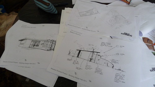
A Guide to Drawing Architectural Plans
 Architectural plans are well-known to anyone who has worked in the building and construction trade, as well as any child who has ever watched an episode of Tom and Jerry or a Warner Bros. cartoon featuring Wile E. Coyote.
You know what they are – a set of 2D drawings of a house or building, which illustrate all the dimensions of the property still to be constructed, as well as the components which will be used and where the various rooms will go.
Most people would instantly recognise the floorplan, the top-down view of the building’s room layout. It allows you to experiment with how you want the property to be laid out, and plan where you want things like sofas or bathroom fixtures to go.
If you’re a newbie to the world of architecture, you might be curious about these plans and wish to try drawing up some of your own. Thankfully, it’s pretty simple to do, and it’s possible to do it for free!
Getting Started
All you really need is a connection to the internet and a half decent computer. Open up your internet browser and you can download one of a number of free CAD (computer aided design) programmes. You can get better ones if you pay for them, but it’s unlikely you’ll need all the extra bells and whistles, so we’ll just recommend Blender and Google SketchUp.
Get to Drawing
Click the “box primitive” tool; you’ll find this under “Create” or “Draw.” Click and drag within the window until the box is of the size you’re looking for – this “box” is the main structure of the property, the outside walls.
This is just to get you started, so don’t worry if you don’t want to create a standard house: once you’re accustomed to the tools you can use this guide to create more complicated structures. CAD programmes can be used to create just about anything – bridges, stadia, churches; you name it!
Interior Design
Remember – what you’re using now is more or less the same as any architect would use, including those working for big firms like McCormick Architecture. These programmes are really versatile.
Now you want to find the “wireframe” or “transparency” tool and use this on the box. This will turn the interior transparent; now you can add more boxes within the larger one to represent the separate rooms.
Add Dimensions
Using the “top” view, utilise the “measure” tools to find out the lengths of each box, if they’re not already displayed. Now you need to create the dimension lines.
Draw lines of equal length parallel to each segment, and put a small distance between the two. Now draw arrows to bookend the line, then erase a small space in the middle of the line. In this new space, you can write the measurement of the line.
Once you’ve done this with all your rooms, you have a completed “top” view! All you need to do is apply the above steps to a “front” and a “side” view, and you’ve completed your plans – great!
Not needed
More to Read:

Previous Posts: